OBN
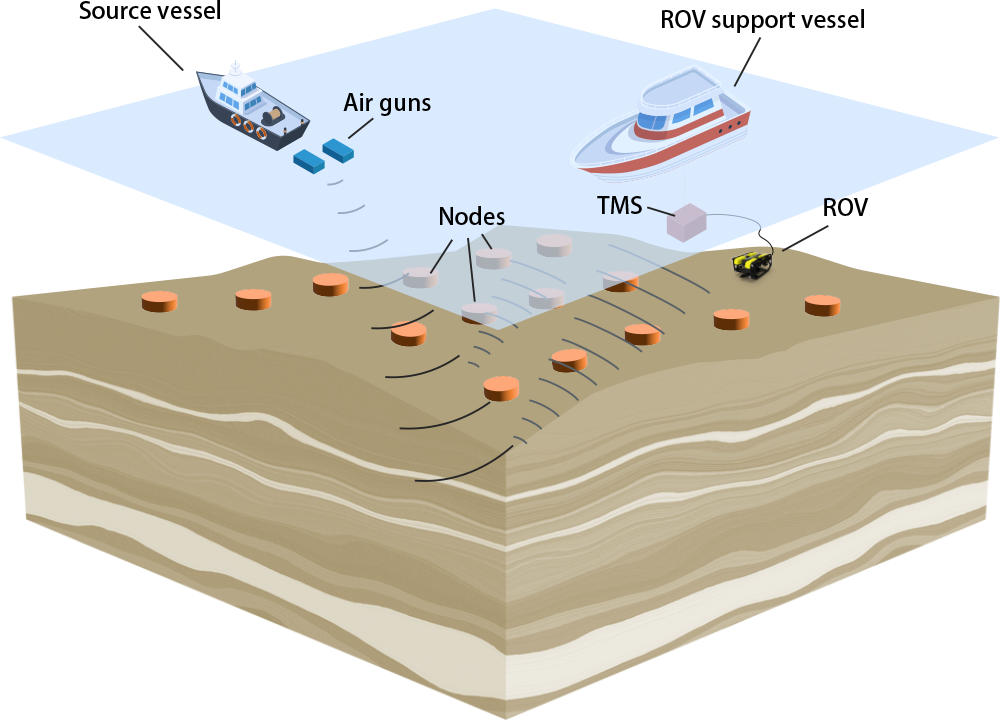
Ocean Bottom Nodes (OBN) are marine seismic survey devices used to record vibrations on the seabed. Unlike traditional cables, they can be freely placed on the seabed (see Figure 1). They can be used at depths ranging from tens to thousands of meters. Seismic survey using OBN has the following advantages:
- Compared to marine streamer survey methods, it can obtain seismic data with wider azimuths and longer offset distances, providing higher resolution subsurface images.
- It is less affected by surface noise such as waves and ship traffic.
- It can obtain not only pressure data but also three-component vibration data, providing more geological information.
- It can be used in areas where traditional cable survey methods are impractical, such as near oil platforms or in complex seabed topographies.
“Tansa” is usually operated in waters deeper than 50 meters for safety reasons. However, with the recent increase in CCS and renewable energy development activities, there is a growing demand for seismic exploration in shallow waters less than 50 meters deep.
Therefore, OGF aims to expand the range of seismic survey using the latest OBN technology even in areas where “Tansa” has difficulty accessing. OGF is expanding technical networking with experienced OBN survey companies to achieve advanced and cost-effective 3D OBN survey.”

4D Monitoring
Repeating 3D seismic surveys at certain time intervals is called 4D (four-dimensional: three spatial axes + time axis) seismic survey. This is a highly effective method for detecting changes in physical properties such as fluid substitution and pressure variations within target underground reservoirs and strata. Seismic waves are affected by these changes in physical properties, resulting in differences in the final 3D seismic survey images. This feature is widely used in many monitoring projects.
However, during the preliminary applicability study phase, the following points need to be confirmed:
- Repeatability of seismic surveys
- Magnitude of seismic wave response to changes in physical parameters
- Optimal design of 3D seismic surveys
- Planning of 3D seismic survey timing
On the other hand, since 4D seismic survey is relatively high-cost, more targeted and cost-effective monitoring methods such as seismic survey using Distributed Acoustic Sensing (DAS) with optical fibers are also proposed as alternatives. However, as suggested in some projects, there is always the possibility of unforeseen phenomena occurring. 4D seismic exploration is expected to reduce the risk of missing unexpected phenomena by enabling more comprehensive monitoring.
OGF is striving to make 4D seismic exploration more accessible by reducing exploration costs through optimal survey design and improved operational efficiency.
Imaging technology using multi refection
In marine seismic survey, multiple reflections*1 are considered noise, and the following three approaches are being researched and developed for their removal:
- Methods that utilize the differences in characteristics between primary reflections*2 and multiple reflections.
- Methods that implement multiple reflection modeling.
- Methods that directly predict multiple reflections from the recorded data.
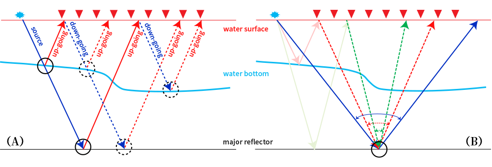
The widely used SRME*3 method falls under category (3), modeling and subtracting only the multiple reflections caused by the sea surface. On the other hand, imaging using modeled multiple reflections is also being attempted. Sea surface multiple reflections are considered to be composed of two or more primary reflections separated by sea surface reflections, and all these processes are included in the recordings (see Figure 2(A)). If upward and downward going waves at the sea surface can be obtained using the sea surface multiple reflections modeled by SRME, multiple reflection images can be obtained by applying the reverse and forward propagation and imaging principles.
In practice, imaging of multiple reflections can be achieved by using the separated upward and downward going waves as the receiving and transmitting wavefields. This method is called Separated Wavefield Imaging (SWIM). SWIM allows for high-resolution imaging due to increased illumination at the reflection points (see Figure 2(B)).
The geostreamer data acquired by OGF through “TANSA” has the advantage of facilitating the separation of upward and downward going waves, and SWIM can be applied using the PGS SPArK data processing software that OGF routinely uses.

*1 A multiple reflection occurs when seismic waves reflect multiple times between subsurface layers before returning to the surface. These reflections are treated as noise compared to primary reflections, complicating the analysis of subsurface structures. Techniques like SRME are employed to remove multiples and improve data quality.
*2 A primary reflection is the first seismic wave that reflects off a boundary between different subsurface layers during seismic exploration. This wave returns to the surface without interacting with other reflections, providing key information about the main subsurface structures. Analyzing primary reflections is crucial for accurately mapping stratigraphy and resource exploration.
*3 SRME (Surface-Related Multiple Elimination) is a technique used in seismic exploration to remove surface-related multiple reflections from seismic data. This enhances data accuracy and provides clearer imaging of subsurface structures, particularly when strong reflections from shallow layers are present.
